OpenTouch S3
A modern remake of the Bare Conductive Touch Board: the same 12 crocodile-clip electrodes and MP3 player, rebuilt around an ESP32-S3 with USB-C, a proper LiPo power path, WiFi, Bluetooth, line-in, MIDI out and Qwiic.
Status: Rev B1 design is complete and passes KiCad DRC with 0 unconnected pads and 0 clearance errors. It has not been fabricated or tested yet. Review the layout in KiCad before ordering.
The board
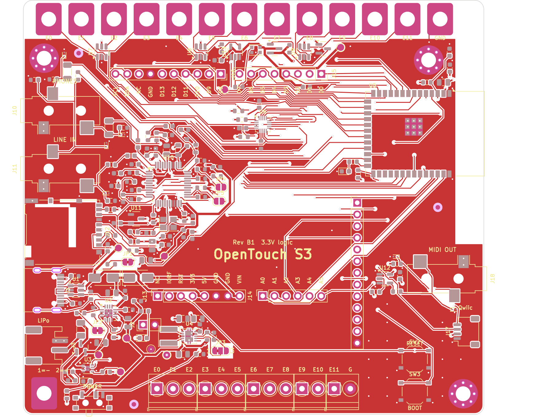
What's on it
- Brain
- ESP32-S3-WROOM-1-N16R8: dual-core 240 MHz, 16 MB flash, 8 MB PSRAM, WiFi, Bluetooth LE, native USB. Pre-certified radio module.
- Touch
- NXP MPR121, 12 electrodes at I²C 0x5C (same as the Touch Board). Crocodile pads, 3.5 mm screw terminals and a 2.54 mm header. ESD diodes on every electrode.
- Audio
- VS1053B codec: MP3, OGG, AAC, WAV, FLAC and a General MIDI synth. Headphone out, stereo line-in for recording, microSD.
- Power in
- USB-C (works with C-to-C cables), 1-cell LiPo on JST-PH, or 4.5-10 V on the VIN pin. Input over-voltage protection to 10.5 V.
- Battery
- BQ24074 power-path charger (500 mA, or 250 mA via JP1), reverse polarity MOSFET, 1.1 A PTC fuse, MAX17048 fuel gauge.
- 3.3 V rail
- TPS63001 buck-boost: stays at 3.3 V from a full to an empty LiPo. The switch turns the board off while charging continues.
- MIDI
- MIDI OUT on a 3.5 mm TRS type A jack (tip = pin 5, ring = pin 4) with 3.3 V signalling (MMA CA-033). USB MIDI and Bluetooth MIDI in firmware.
- Expansion
- Arduino R3 header pattern (3.3 V logic), Qwiic / STEMMA QT, WS2812B RGB LED, BOOT and RESET buttons, test points on every rail.
How it's wired
Full wiring is in the schematic PDF (5 sheets). This is the signal flow.
flowchart LR
  USB[USB-C] -->|VBUS| ESD1[USBLC6 ESD] --> CHG[BQ24074
power path]
  VIN[VIN 4.5-10V] --> CHG
  BAT[LiPo JST-PH] --> PROT[Reverse FET + PTC] --> CHG
  CHG -->|VSYS| REG[TPS63001
3.3V buck-boost]
  PROT --> FG[MAX17048
fuel gauge]
  REG -->|3V3| ESP[ESP32-S3
WROOM-1]
  USB -->|D+ D-| ESP
  ESP <-->|I2C| MPR[MPR121 touch]
  ESP <-->|I2C| FG
  ESP <-->|I2C| QW[Qwiic]
  MPR --- EL[12 electrodes
pads + terminals]
  ESP <-->|SPI| VS[VS1053B codec]
  ESP <-->|SPI| SD[microSD]
  VS --> HP[Headphone jack]
  LIN[Line-in jack] --> VS
  ESP -->|UART| MIDI[MIDI OUT TRS]
  ESP --> RGB[WS2812B LED]
What changed from the Touch Board
| Area | Original | OpenTouch S3 |
|---|---|---|
| MCU | ATmega32U4, 16 MHz, 5 V | ESP32-S3, 240 MHz, WiFi + BLE, 3.3 V throughout (no level shifters) |
| USB | Micro-USB | USB-C with CC resistors and USBLC6 ESD protection |
| Charging | MCP73831, 200 mA, diode OR-ing | BQ24074 power path with OVP, 500/250 mA, battery NTC option |
| Regulation | Boost to 5 V then LDOs | Single buck-boost to 3.3 V, 1.8 V LDO for the codec core |
| Battery | PTC only | Reverse polarity FET, PTC, fuel gauge |
| Touch | Crocodile pads + header | Adds screw terminals and ESD diodes on all 12 electrodes |
| Audio | Headphone out | Headphone out + stereo line-in (record to SD) |
| MIDI | Internal synth only | Internal synth + MIDI OUT jack + USB/BLE MIDI |
| PCB | 2-layer, 85 × 63 mm, 0402 parts | 4-layer with solid GND and 3V3 planes, 100 × 90 mm, 0603 parts (JLCPCB basic) |
Pin map
| Function | ESP32-S3 |
|---|---|
| I²C SDA / SCL | IO8 / IO9 |
| MPR121 interrupt | IO10 |
| SPI MOSI / SCK / MISO | IO11 / IO12 / IO13 |
| microSD CS | IO14 |
| VS1053 XCS / XDCS | IO15 / IO16 |
| VS1053 DREQ / XRESET | IO17 / IO46 |
| Serial MIDI → VS1053 (JP5) | IO18 |
| MIDI OUT | IO47 |
| RGB LED / L LED | IO48 / IO45 |
| USB present (active low) | IO21 |
| Header | ESP32-S3 |
|---|---|
| A0 A1 A2 A3 A4 A5 | IO1 IO2 IO4 IO5 IO6 IO7 |
| D0 RX / D1 TX | IO44 / IO43 |
| D2 / D3 (SDA / SCL) | IO8 / IO9 |
| D4 (touch IRQ) | IO10 |
| D5 D6 D7 | IO3 IO41 IO42 |
| D8 D9 D10 | IO38 IO39 IO40 |
| D11 D12 D13 | IO11 IO13 IO12 |
| VIN | 4.5-10 V in |
| 5V | USB VBUS only |
All I/O is 3.3 V. Don't connect 5 V signals to the header pins.
Solder jumpers
| Jumper | As built | Change it to |
|---|---|---|
| JP1 | Bridged: 500 mA charging | Cut for 250 mA (cells under 500 mAh) |
| JP2 | Bridged: no battery thermistor | Cut when you fit a 10 k NTC to J2 |
| JP3 | 1-2: power-save mode | 2-3: forced PWM, lowest audio noise |
| JP4 | Open | Close to boot the VS1053 as a real-time MIDI synth |
| JP5 | Open | Close to send serial MIDI from IO18 into the VS1053 |
Ordering at JLCPCB
- Upload the Gerber zip. Pick 4 layers, 1.6 mm, ENIG finish so the touch pads stay clean.
- Turn on PCB Assembly, top side, and upload the BOM and CPL files.
- In the placement preview, confirm pin 1 on U2, U3, U4, U5, U6 and U10 and the connector orientations.
- Headers J2, J9 and J13-J16 are left unfitted on purpose. Solder them yourself if you want them.
Power from a USB-C charger where you can: the input limit is about 1 A, which a 500 mA laptop port may not supply with WiFi busy and a battery charging. Never feed power into the 5V header pin; use VIN.
First power-up
- Unpowered, check TP1 (VSYS) and TP2 (3V3) read well above 100 Ω to TP4 (GND).
- Plug in USB-C with the switch on. The green PWR LED lights, TP2 reads 3.3 V and TP1 about 4.4 V.
- The board shows up as a USB serial port. If it doesn't, hold BOOT, tap RESET, release BOOT.
- Arduino IDE: "ESP32S3 Dev Module", USB CDC on boot enabled, OPI PSRAM, 16 MB flash.
Software
| Part | Library | Setup |
|---|---|---|
| MPR121 | Bare Conductive MPR121 or Adafruit_MPR121 | address 0x5C, IRQ IO10, Wire.begin(8, 9) |
| VS1053B | Adafruit_VS1053 | SPI.begin(12, 13, 11); player(46, 15, 16, 17, 14) |
| MAX17048 | SparkFun MAX1704x / Adafruit_MAX1704X | address 0x36 |
| RGB LED | Adafruit_NeoPixel / FastLED | IO48, 1 pixel |
| MIDI OUT | Arduino MIDI Library | Serial1 TX = IO47, 31250 baud |
Touch Board sketches port mostly by changing pin numbers. The MPR121 address and electrode numbering are unchanged.